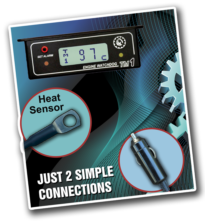
Mounting the Unit (TM1 suits any engine)
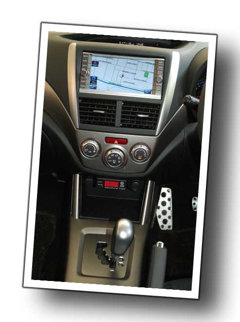
- Mount the unit in the cabin of the vehicle where it can be observed by the driver
- Run the heat sensor wire neatly to the engine ensuring not to pull on the sensor lug
- Ensure the wiring is not likely to be damaged by such things as hot exhaust pipes, spinning fan blades or be crushed or cut when running through engine bay hatches or fire walls
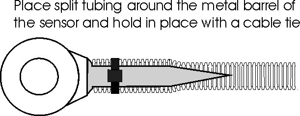
- Starting on the metal part of the red heat sensor, place the split loom tubing over the sensor cable and secure it as per the diagram below. Secure the cable allowing for movement of the engine.
- Note: DO NOT over tighten cable ties and crush the sensor cable.
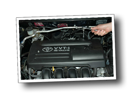
Mounting the Sensor
- Mount the sensor where it will reflect the engine temperature correctly, or as near the heat source as possible. eg. Under a rocker cover bolt, a bolt on the block near the heat source (away from the exhaust ports if possible) or a thermostat housing bolt ( Note: Avoid using the thermostat bolt if it is well away from the block).
- If possible, avoid running the sensor wire close to the ignition leads or the exhaust system.
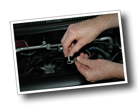
- If you need to enlarge the sensor hole, file it out. Do not use a drill, as it will bie into the brass and spin.
- Do not clamp the barrel of the sensor in a vice.
- Always restore any bolt back to the manufacturer’s recommended tension.
Cutting and Joining the Sensor wires
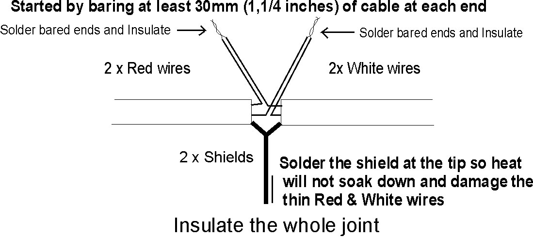
- It is ok to cut or lengthen the sensor wire provided it is done at the display end. (Note - The sensor cable is a shielded lead).
- While soldering is the preferred method of joining, it is ok to clamp the ends using the supplied terminal block. Ensure it is well supported and not exposed to moisture. (Wires are thin, so double check your joints).
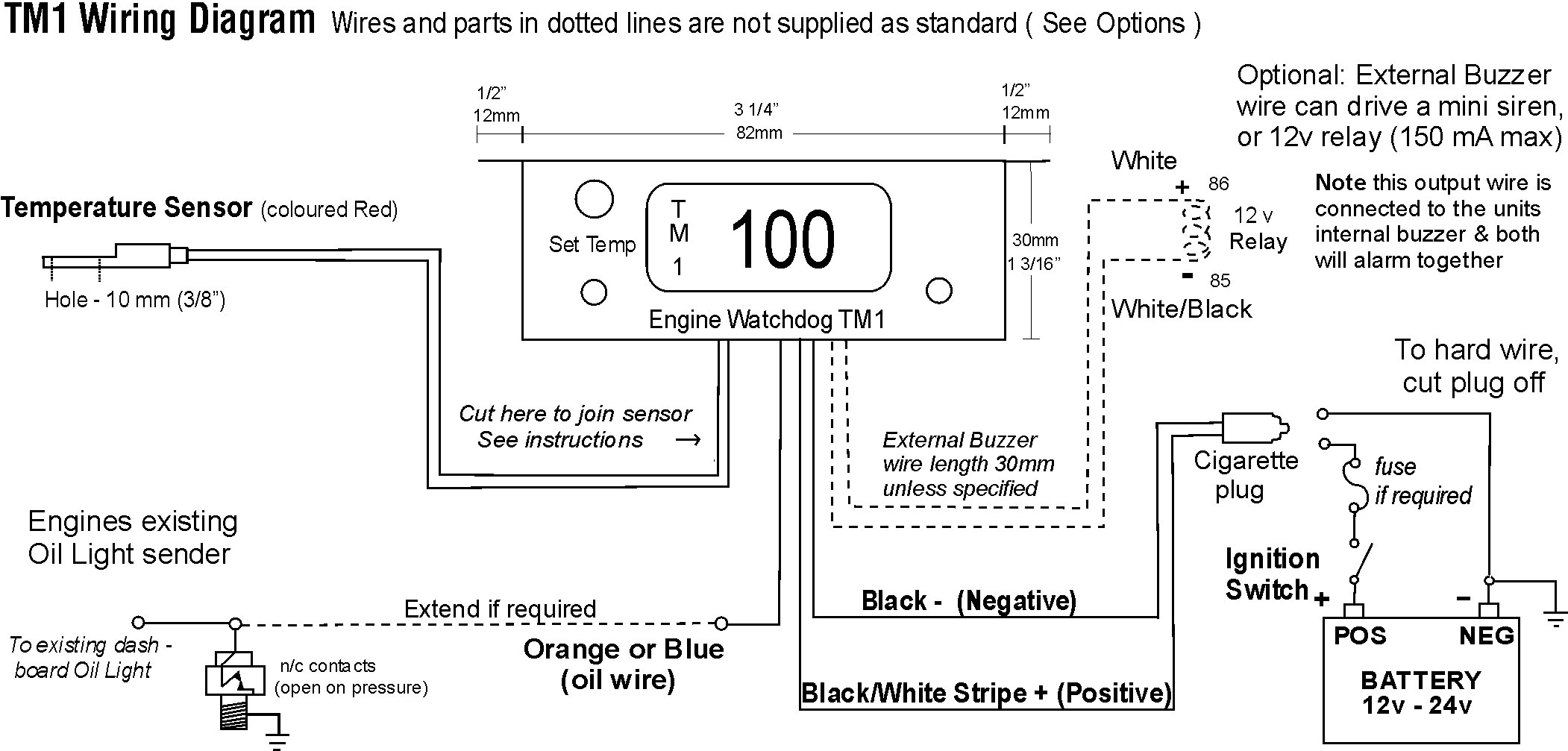
Connecting the Power
- The cigarette plug can be plugged into any 12 or 24 volt DC system.
- Hard wiring – Cut the plug off and split the wires apart, Connect the fully black half of the power cable to the battery negative or vehicle chassis (see wiring diagram over)
- Next connect the Black/White half of the power cable to the battery positive via the ignition switch.
- Fuse if required, 1 amp fuse
Connecting the optional, Low Oil Pressure Alarm
- This option is only suitable for vehicles that have an existing dash mounted oil light that is controlled by a standard car type oil light sender. NOT SUITABLE FOR GAUGES. If you do not have an oil light and want this feature, fit an inexpensive oil light sender to the engine (contacts normally closed, open on pressure)
- Extend the orange (or blue) wire and run it to the oil light sender on the engine
- Connect the orange (or blue) wire to the top of the oil sender along with the existing oil light wire, when the light is ON the alarm will sound. NOTE the Oil alarm is delayed for 10 seconds to allow for engine starting.
Where to set the Alarm Temperature
- Firstly observe the engines highest normal running temperature over several days of driving, or after this time interrogate the unit’s highest temp memory (if you have an electric thermostatic fan observe when it starts).
- Set the alarm at a higher temperature, depending on the degree of sensitivity required, 5 – 10 degrees C, or (10 to 20 degrees F) is normal.
Operating the TM1
- See the Operating Guide provided, or see a copy at enginewatchdog.com Click on TM1 and then, TM1 Operating Guide at the top of the page.
To test the alarm
- By reprogramming the alarm temperature so it is lower than the current engine temperature, the alarm will sound. Set the alarm temperature back to its correct position when finishing the test.
Operating the TM1
- See the Operating Guide provided, or see a copy at enginewatchdog.com Click on TM1 and then, TM1 Operating Guide at the top of the page.
Trouble Shooting Also see the Operating Guide to interpret the fault messages
- Unit will not come on - Check for power - Check for reverse polarity - See ‘Connecting the Power’ in the instructions.
- Display reads 127C (257F) and alarm is on – Unit has reached its maximum operating temp, move sensor location to a cooler location
- Display just reads 85C (185F) – Red wire in sensor cable is damaged, repair or replace sensor (see Operating Guide).
- Low Oil feature will not work – Shorting the Orange (or Blue) wire to negative will test this feature.
- After stopping the engine, the engine temperature continues to go up a lot higher than when it is normally running. A small increase in engine temperature is normal after stopping, however if the increase is excessive the heat sensor may need to be moved to a location that is more reflective of the engine temperature