
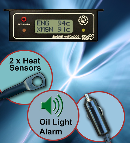
Mounting the Unit (TM4 suits any engine)
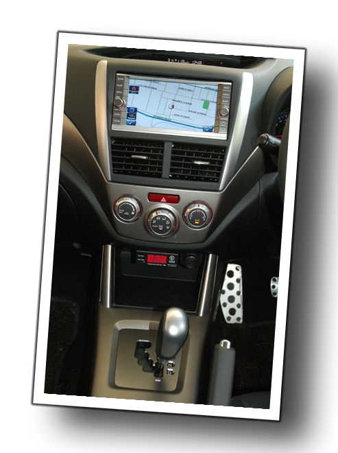
- Mount the unit in the cabin of the vehicle where it can be observed by the driver.
- Run the temperature sensor wire neatly to the engine ensuring not to pull on the sensor lug.
- Ensure the wiring is not likely to be cut or crushed when running them through engine bay hatches or fire walls.
- Starting at the sensor, place the spiral wrap provided around the sensor cable and secure.
- NOTE If using large cable ties, DO NOT over tighten them and crush the sensor cable.

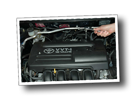
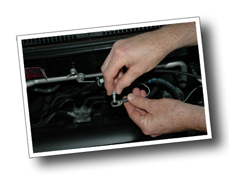
Mounting the Sensor
- Mount the sensor where it will reflect the engine temperature correctly, or as near the heat source as possible. Examples are under a tappet cover bolt that is away from the exhaust ports or a thermostat housing bolt that is close to the block.
- Always restore any bolt back to the manufacturer’s
recommended tension. - If possible, avoid running the sensor wire close to the ignition or the exhaust system.
-
To enlarge the sensor hole, carefully file it out, do not use a large drill. Do not clamp the barrel of the sensor in a vice.
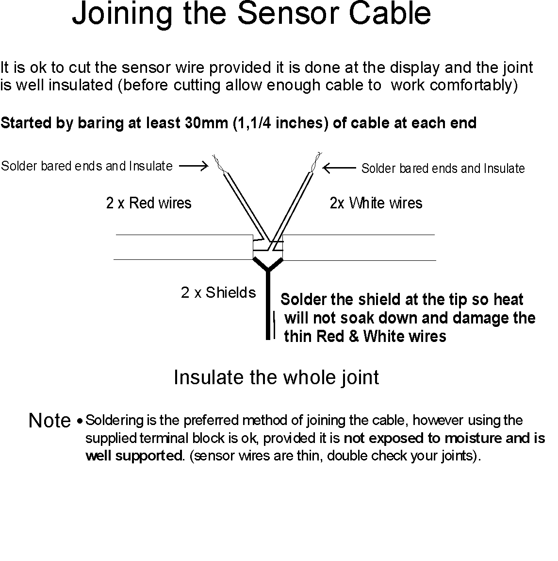
Cutting and Joining the Sensor wires
- It is ok to cut or lengthen the sensor wire, provided it is done at the display end. (NOTE - The sensor cable is a shielded lead). Use either method described below.
- Soldering is the preferred method of joining the cable. To join, remove at least 30mm of the outer plastic at each end of the cable. Separate the wires and loosely twitch the shield strands together. Splay the white wire, the red wire and the shield out like three fingers. Strip about 5mm of the plastic off the ends of the red and white wires. Lay the wires together and twist the ends of the two red wires, the two white wires and the two shields together ensuring no other colour or strand of the shield is touching any other colour. Solder the tips of the wires ensuring not to let too much heat go down the shield and damage the red or white wires. Insulate each wire so they cannot touch any other then insulate the whole joint.
- Using the supplied terminal block is ok, provided it is not exposed to moisture and is well supported. Wire similar to above only clamp the ends instead soldering them (Inner wires are thin, so double check your joints)
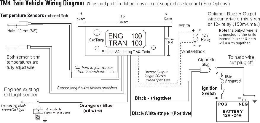
Connecting the Power
- Plug the cigarette lighter plug into the socket of any 12 or 24 volt DC system.
- Hard wiring, cut the plug off and split the wires apart.
- Connect the red/black half of the power cable to the battery negative or vehicle chassis.
- Next connect the red half of the of the power cable to the battery positive via the ignition switch (See Diagram below).
- The unit is suitable for 12 or 24 volt DC systems and is fully reverse polarity protected.
- Fuse if required, 1 amp fuse.
Connecting the optional, Low Oil Pressure Alarm
-
This option is standard on TM4's and is only suitable for vehicles that have an existing dash mounted oil light that is controlled by a standard oil light sender. NOT SUITABLE FOR GAUGES. If you do not have an oil light and want this feature, fit an inexpensive oil light sender to the engine (contacts normally closed, open on pressure).
-
Extend the orange wire and run it to the oil light sender on the engine.
-
Connect the orange wire to the top of the oil sender along with the existing oil light wire, when the light is on the Alarm will sound. NOTE the Oil alarm is delayed for 10 second to allow for engine starting.
Where to set the Alarm Temperature
- If possible, run the engine until the thermostatic fan cuts in, or observe the highest engine temperature over several days of running.
- Set the alarm at a higher temperature, depending on the degree of sensitivity required, 5 – 10 C is normal.
Operating the TM4
- See the Operating Guide, a copy is available at enginewatchdog.com
- Click on TM4 and then, TM4 Operating Guide at the top of the page (for twin sensor version then scroll down)
To test the alarm
By reprogramming the alarm temperature so it is lower than the current engine temperature, the alarm will sound. Set the alarm temperature back to its correct position when finishing the test.
Troubleshooting
Also see the Operating Guide to interpret the fault messages
- Unit will not come on - Check for power - Check for reverse polarity - See ‘Connecting the Power’ in the instructions.
- Display reads 127 and alarm is on – Unit has reached its maximum operating temperature, move sensor location to < 127 degrees C.
- Display just reads 85 – Red wire in sensor cable is damaged, repair or replace sensor (see Operating Guide).
- Low Oil feature will not work – Shorting the orange wire to negative will test this feature.
- After stopping the engine, the engine temperature continues to go up a lot higher than when it is normally running. A small increase in engine temperature is normal after stopping, however if the increase is excessive the heat sensor may need to be moved to a location that is more reflective of the engine temperature.
PURCHASE & CONTACT INFORMATION
HOME | HEAT SENSOR |